A Problem Solving Mind
In this chapter, we introduce a model of mind that scientists have developed over years for describing the problem-solving part of the brain. We will show how the structure of our mind directly affects the way we understand and organise systems. Then we will introduce methods that can be used to assist our mind in solving problems.
Memory organisation and limitation
The way we think and organise entities is directly influenced by our mind. To understand why engineers represent engineering systems in the form of systems and subsystems, we must understand how our mind organises and processes information. The reason why this is important is because; humans perceive the real world in terms of concepts and skills of conceptual representation of systems can be greatly improved by studying the mind that stores and processes these concepts. Examining and learning about one’s mind is called metacognition.
noun (Psychology) awareness and understanding of one's own thought processes, esp. regarded as having a role in directing those processes.
Before we introduce the present theoretical model of the basic inner working of our memory, we shall go through a couple of examples to clarify its limiting property that defines how we perceive the world. We start by asking, why some mental tasks in life are overly simple to accomplish and some are not? A single-digit arithmetic calculation in mind, for example, is overly simple for most of adult people. But the same calculation with multiple digits becomes quite difficult to attain without external assistance. Let us go through these examples more narrowly and see their differences.
When we add two single-digit numbers in our mind, say "3 + 4", the mind starts the addition by recollecting concepts behind the meaning of the numbers and conceptual knowhow about adding them. The operation requires tracking of only several meanings at the same time before a result can be obtained. As we increase the number of digits, we need more places for the numbers to hold and more tracking of the individual steps that the process produces. At some point, the calculation becomes impossible in our mind and we require external assistance, such as a pencil and a paper, to store and track the steps of the process. Note that the procedure and the given information about the two additions are perfectly similar yet one is simple and the other is not. Whether adding single-digit or multiple-digit numbers, we are applying the same method to reach a result; the given facts about the calculation and the applied method for the calculation are absolutely the same for the two processes. As we will see later, our ability to store and track items in our mind at a time is limited to 7, plus or minus two. We will come back to these examples shortly.
Our current theoretical model of the problem solving mind has three major parts:
- Short-term memory: is a small memory for storing pieces of information that are currently processed. It is very limited in capacity compared with the long-term memory.
- Long-term memory: is a large memory section of the brain for storing facts, concepts and relationships. Anything we learn is permanently kept here. Knowledge of what things are and knowledge of how to solve problems is formed here. There’s no known capacity limit to this memory.
- Thought processor: manipulates and processes information in the short-term memory that result in conclusions and actions.
Through our biological senses (sight, hearing, smell, taste and touch), information is first stored in short-term memory. If information was not successfully transferred to long-term memory within seconds, it is discarded. Any processes of information, by the thought processor, are carried out through the short-term memory. This means that, even permanently stored concepts or information in the long-term memory must first be transferred back to short-term memory before the thought processor can process them. Figure 1 shows a sketch of this model.
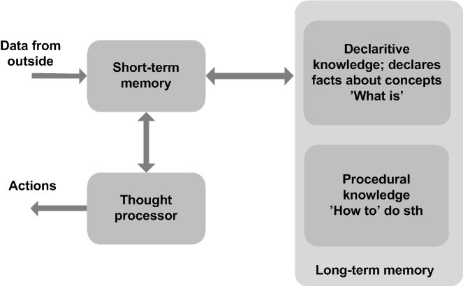 |
| Figure 1. A general sketch of the problem solving mind |
Research and experiments show that the number of separate, unrelated items that the short-term memory can hold at any particular time is 7, plus or minus 2, depending on people. Short-term memory saturates (becomes full) when people face situations that require the storage of more than the suggested number of items. This is what happens when people try to mentally perform an arithmetic calculation that has more than 9 separate steps to solve. Tracking more than 9 items in memory is getting harder and, at some point, becomes impossible. As we will see later, this is directly connected to engineering problem solving. Figure 2 depicts key facts about short-term memory.
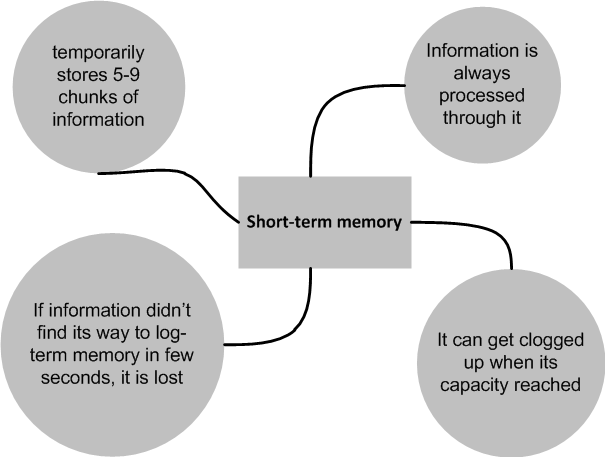 |
| Figure 2. Key facts about short-term memory |
With the limits of the short-term memory capacity, human mind has a spectacular way to circumvent this limit through chunks and relationships. The limited items that the short-term memory can hold can be chunks of information. The term “chunk” is a classic term which has been used to date. A word, for example, is a chunk of letters. If we could hold 7 unrelated words in our short-term memory and if a word was 5 letters, then that totals to 35 letters all together. The short-term memory can hold that many letters only in groups or chunks. However, the number of chunks, for most of people, still cannot go beyond 9. The number of items that the short-term memory can hold at any particular time, therefore, is 7 chunks, plus or minus 2, regardless of what the chunks might represent. Chunks can be formed from other chunks; letters form word-chunks and chunks of words, sentences. This is illustrated in figure 3.
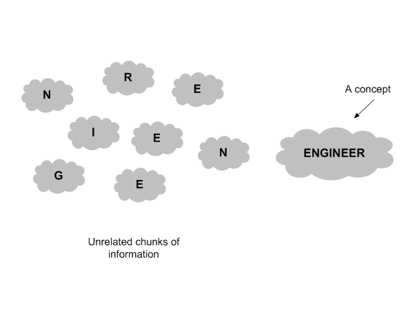 |
| Figure 3. Individual letters of the term engineer combined to form the term itself. Short-term memory can hold more than 9 letters in the form of words which are chunks of letters |
Information is transferred to/from long-term memory in chunks. But how chunks are organised and accessed in long-term memory? The answer is, via a relationship which is technically known as schema. Knowledge is a collection of concepts in the long-term memory. The concepts are linked together through schemas (or schemata which is its plural). Related chunks of information or knowledge are organised under a central concept. Individual facts are small chunks of information that connect concepts together through relationships. It is because of scanning through relationships and concepts that we can recollect a fact from long-term memory. To transfer a chunk of new information, or a new fact, from short-term memory to long-term memory—this is tantamount to learning a new skill or understanding a new fact or concept—a new relationship must first be formed between the new information and an existing concept in the long-term memory. Figure 4 shows a sketch of the concept of schema.
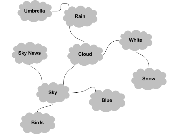 |
| Figure 4. A diagram of a schema. 'Sky' concept reminds us of concepts such as 'Blue', 'Sky News', and 'Cloud'. 'Cloud' concept, in turn, reminds us of concpets such as 'White' and 'Rain'. |
As it can be seen in figure 4, schemata are links between different concepts. When we recall the concept of sky, for example, our mind automatically recalls related concepts that are already stored in the long-term memory. And each individual concept has its own related concepts. In this particular case, "Sky" is a central concept.
The long-term memory stores definitions and also skills of how to do something. Two types of knowledge are stored in it. They are declarative and procedural types. A declarative knowledge enables us to define objects. It is often referred to as ‘what is’ knowledge. A procedural knowledge, on the other hand, is knowledge and skills that empower us to solve all kinds of problems in an algorithmic way. This knowledge allows us to tie our present decision to some premise or prerequisites. It is often referred to as how-to or know-how knowledge.
return top
Assisting mind - IF and THEN Statements
By chaining together chunks of knowledge from long-term memory, humans can solve complex problems. With a series of conditional statements, for example, we can reach impressive conclusions. The if… then… statements are the most popular way people reach conclusions:
| IF | some condition |
| THEN | conclude or act |
The moment we start an 'if' statement, schemata take control and our mind begin to automatically invoke related concepts and transfer them into the short-term memory. If we were to start with if it is raining ..., for example, the concept of rain brings to our mind a collection of related concepts such as raincoat, wetness, umbrella, etc. When we examine this type of reasoning more narrowly, we would see that the condition statement is a fact or a chunk of facts that may or may not be already known to the long-term memory. The conclusion or action part of the above may add new declarative knowledge to long-term memory; this means that we may learn new things through the conclusion. Figure 5 highlights IF statement.
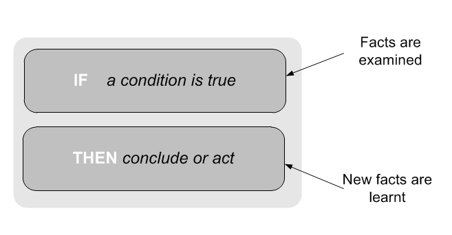 |
| Figure 5. The IF THEN reasoning |
The IF-THEN reasoning is the bases of computer programming where conditional statements changes the normal flow of programmes based on true conditions. We will say more about computer programmes when we later introduce flow chart diagrams. With the use of procedural knowledge and a set of facts, we are able to reach logical conclusions such as identifying objects, as the following example demonstrates:
| IF | it is fruit |
| AND is yellow | |
| AND is elongated | |
| THEN | it is a banana |
An object can be identified only when a set of facts about the object exist at the same time. The use of AND and OR is to add extra information in the conditional statement. In short, if all conditions are true, then a certain conclusion is likely. If one or more facts are dubious, more examination has to be conducted.
return top
Assisting mind - Chaining or Solving Problems in Steps
Because of complexity, oftentimes we need to break down solutions of certain problems into individual steps. Then solve the steps one after the other in a chain. This is called chaining since you chain together solutions of steps that lead to a final solution. Figure 6 below shows three possible ways of chaining.
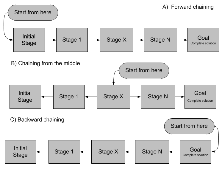 |
| Figure 6. Three directions of chaining: A, B, and C |
As it can be seen in figure 6, chaining can be pursued in three different directions. Forward chaining starts from the initial stage of the problem and work toward the goal or solution. Backward chaining begins at the goal and steps back in the direction of the initial stage of the solution. Another possible chaining is to start somewhere in the middle stages of the solution, chaining from the middle, and pursue in opposite directions towards both its initial and final stages. All the three chaining are used and are equally important in solving problems. Next, we’ll explore some examples to clarify them.
To illustrate chaining, imagine that you are trying to tie together two strings hanging from the ceiling of an empty room given a chair and a pair of pliers only. The hanging ends of the strings are too high for you to reach and the strings are fixed at the ceiling so there is no way to move them. The distance between the strings is such that if you reached one of them, you won’t be able to reach the other with your bare hands. How would you tie the strings? Figure 7 below depicts the room.
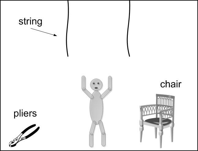 |
| Figure 7. The room and the strings problem |
A number of lessons are to be learnt from this seemingly simple problem. Questions such as “why a pair of pliers is left in the room?” immediately preoccupy the mind. While our mind—the schema—automatically recalls the linked concepts to the chair, for example elevation, the pliers don’t have an obvious use in this situation. The schema keeps recalling “cut” and “grab” concepts which have not much to do with our problem.
“Each time we face a new problem, our mind creates new links to the knowledge we already possess.”
Before we tackle this problem, it is good to know that learning physically alters the links between the nerve cells in the brain. Another important fact about learning is that, not all parts of the brain may be ready for changes in its structure at the same time; some parts may be ready and some parts may not. This is why some times it is good practice to go away from a problem and come back to it at a later time.
Chaining forward to tackle the problem
Forward chaining starts from the beginning stage of the problem and work towards the complete solution. The complete solution in this case is the tying of the strings. Here’s how it is planned:
| First chain: | we grab the pliers and use the chair to reach one of the strings |
| Second chain: | we tie the pliers to the hanging end of the string and swing it in the direction of the other string (this step may require some thinking) |
| Third chain: | we get off the chair, move it to the other side so that it is under the other string then get on to reach the other string |
| Forth chain: | while on the chair, we grab the swinging pliers and with it the end of the other string, untie the pliers and now we have both ends of the strings then we simply tie them together |
Chaining backward to tackle the problem
To plan backwardly, we start from the final stage of the solution. The final stage in this case is a tied-together string. Here’s how it is thought:
| First chain: | The strings are tied together |
| Second chain: | I must be on the chair, which in turn must be under one of the strings, and have both ends of the strings at my hands |
| Third chain: | I can only reach one end of the string, therefore the other end must somehow come to me (the pliers must bring it to me!) |
| Forth chain: | The pliers must first swing one of the strings so that I can catch it at the other end |
| Fifth chain: | Therefore, I must first swing one string |
The third way of chaining, i.e. starting from the middle stages of the solution, will not make sense in this problem. Working from the middle, however, is very important in engineering as well as problems similar to those that are related to traffics and flight routes.
An example of chaining from the middle
Imagine that you are trying to travel from point X to point Y. X and Y can be two cities, states, or countries. It is important for you to be at point A on a particular day and at a particular time for a meeting. Figure 8 below shows the available routes. To make sure that you will be present in the meeting, you start planning your journey from point A. You work from point A back to point X and choose the best route for the journey. Then you plan your trip from A to your destination at Y. For example, you start from A and ask: when should I leave, for example, point G in order to reach A at a certain time? This is chaining from the middle.
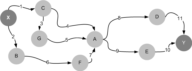 |
| Figure 8. Point X and Y and a bunch of other points that connect them together |
return top
Assisting mind - Concept maps
An important engineering skill is the ability to diagrammatically represent problems and solutions. The limited capacity of our short-term memory compels engineers to use different kinds of diagrams to visualise design problems. One way to assist our mind is by using concept maps. A concept map is a network of concepts built around a central concept. It is a graph with concepts as its nodes and relationships as its links or edges. Concepts are represented with geometrical shapes, usually circles or ellipses, and relationships with labelled lines. Figure 9 below shows a simplified example of a concept map of a computer.
 |
| Figure 9. A simple concept map with computer as its central concept |
Research has shown that the ability to draw a sensible concept map of a system is a mark of understanding of that system. Concept maps are important in that they help create a pattern that can be reused in solving other, similar problems. In short, concept maps are important because:
- they help engineers to brainstorming ideas and assist our minds to further deepen the knowledge of systems
- concept maps can be shared between engineers and hence is a tool for collecting ideas from teams of engineers of different background knowledge
- they test levels of understanding of people, especially engineers, about systems and concepts
- concept maps is an intuitive way of presenting designs and ideas to others
Brainstorming is a way of making a group of people all think about something at the same time, often in order to solve a problem or to create good ideas.
While there are well constructed and useful concept maps that are better in representing systems or ideas, there is no such thing as right or wrong concept maps. They are never fixed or complete; they are iterative and should constantly be modified and refined. With the drawing of a central concept, the mind starts recollecting related concepts that are linked via schemata. Concept maps, therefore, trigger a scan through concepts and relationships in the long-term memory, which you then perceive 5-9 of them at a time through your short-term memory. Since the short-term memory can only hold 5-9 items or chunks of information at a time, quickly drawing the chucks will enable us to map a large number of concepts. Once a preliminary diagram was developed, just by observation, new modifications may be immediately realised. And finally, there’s a constant information exchange between the map and the mind as the diagram grows larger; the map triggers the mind to take new, different routes by creating new links and concepts. This, in turn, will update the concept map and further refine it.
How to draw concept maps?
Drawing concept maps starts with a central concept or domain. This is usually done by addressing a question such as “what is a computer?”. Students who are learning concept maps should start with simple domains in an area that they are familiar with. Examples are the concepts that we encounter everyday such as cars, houses, shops, items we use daily, etc. This way they will learn to draw concept maps quickly and soundly. Another point is the tool that is used for drawing the maps. It is always preferable to use a tool that allows modifications easily without much efforts. We will later introduce a computer application that is particularly designed for drawing concept maps. With such software tools, engineering students can easily and efficiently draw and modify concept maps. Here are a number of effective, good practices when drawing concept maps:
Identify and draw the domain or the central concept. If the question was “what is a computer?” then, obviously, “computer” concept should be our central attention. After that, quickly start to draw around 10 concepts that are related to the domain. Individual concepts should be expressed with one or at most few words. Long sentences indicate that several concepts might have been merged or bound together. In this case, either they should be properly separated or redefined as one concept. Figure 10 shows the result of the first steps.
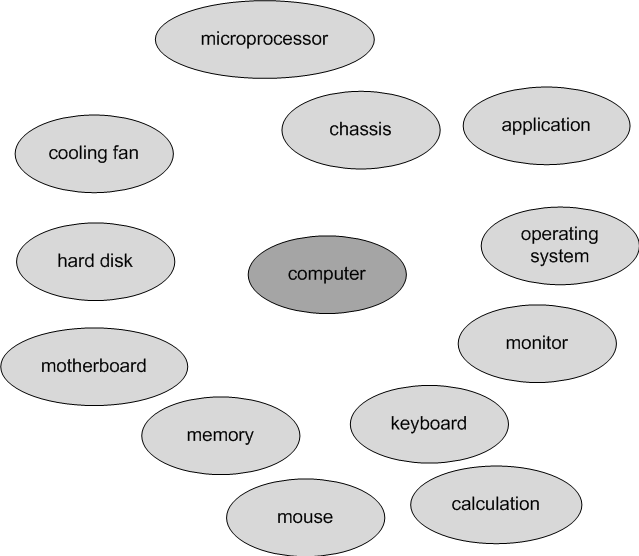 |
| Figure 10. Initial concept map of a computer |
As it is illustrated in figure 10, the initial form of a concept map should have a central concept surrounded by around ten related concepts. Next step is to link the concepts by adding proper relationships. Once again, the labelling of the relationships should be one or a couple of words. Figure 11 shows the map with added relationships. At this stage, the map represents the computer as one large chunk of concepts. This is still not of much help since it mixes different concepts. Next stage is to group related concepts and further simplify the map into multiple chunks.
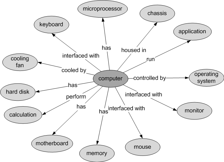 |
| Figure 11. A concept map represents a computer with one chunk of concepts |
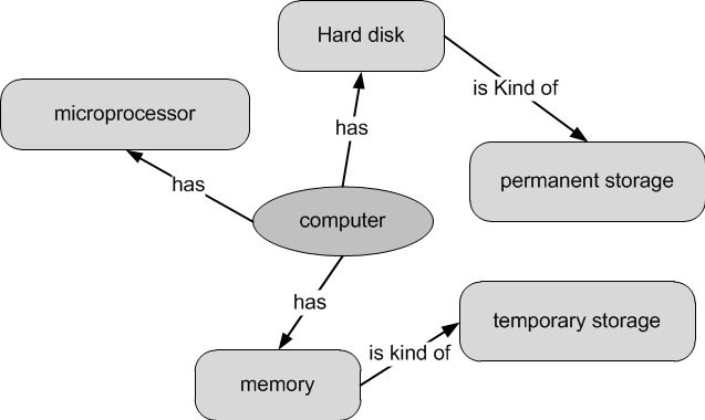
To further simplify the map, we have to define inter-relationships between its individual concepts. This will divide the map into multiple chunks of related concepts. Figure 12 shows the result of this division.
 |
| Figure 12. A concept map of computer in which concepts have been separated into related chunks |
As we can see in figure 12, grouping concepts into chunks help us to get a complete, yet easier picture of systems. This is because the brain has evolved to cope with only limited number of items at a time (recall short-term memory).
“We can see that concept maps are just a form of system-subsystem organisation.”
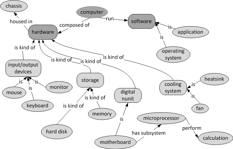
The concept map of figure 12 still lacks additional links that connects the chunks together. For example, there is a close relationship between a microprocessor and a heatsink albeit they are totally different concepts. Heatsinks are designed to cool down microchips such as microprocessors. Fans, on the other hand, ventilate chassis and cool down heatsinks. Identifying additional cross-links often require research. Figure 13 below shows the map with only some additional cross-links.
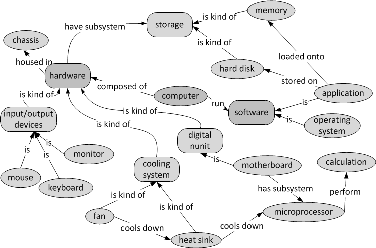 |
| Figure 13. The computer concept map with some additional cross-links |
return top
Assisting mind - Hierarchical system representation
Different systems can be represented in different ways. However, only those representations are effective and useful that account for the short-term memory limitation. When concepts are built round a domain or a central concept, and each concept, in turn, at the centre of yet other related concepts, an organisation of levels or hierarchies are formed. Engineers and scientists tend to form such representation because it is easier and much more effective to recall. Hierarchical representation of systems is fundamental for engineers and scientists.
There are two major forms of hierarchically represented systems. One representation grows outwardly and forms a shape of spider. The other grows in one direction with a root at the starting point to form a tree-like shape. Figure 14 shows these representations.
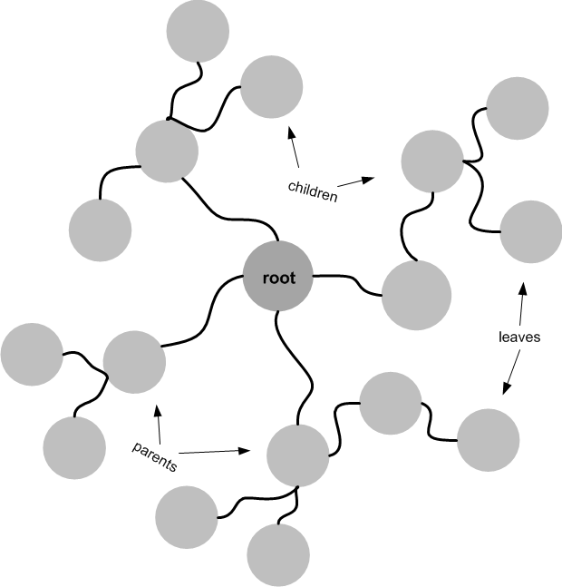 |
| Figure 14. Forms of hierarchical representations spider form |
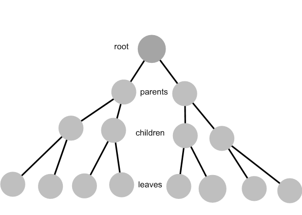 |
| Figure 14. Forms of hierarchical representations tree form |
The nodes of the graphs in figure 14 can be either expressed as parts or classes. Parts hierarchy represent systems in terms of parts and subparts. An engine of a car, for example, can be hierarchically divided into its subparts. Class hierarchies, on the other hand, represent systems in terms of classes. A class represents a collection of concepts with one or more common attributes. Classes are of different abstraction levels. Higher levels are called parent classes from which child classes descend. A parent class is a more general class that describes a family of concepts in broader concepts. An example of a parent class could be a vehicle, which is a general term that describes all kinds of man-made, wheeled objects used for transportation. A child class, by comparison, describes entities in a more concrete manner.
While they have their own attributes, child classes inherit the attributes of their parents. An example of a child class could be a “car” that descends from “vehicle” class. “Car” classes inherit “vehicle” properties but they have their own properties too. A child class of a “car”, in turn, could be a specific model which can have specific attributes such as a type of an engine or certain design properties. As classes descend from each other and form hierarchical layers, they get closer and closer to a more concrete description of the entities in question. A “Toyota” car is more concrete than a general class such as vehicle. A class hierarchy is also called taxonomy.
Taxonomy is the scientific process of classifying things (= arranging them into groups).
Humans classify and group tools and artefacts in terms of functions, rather than other properties such as types of material. We do that because we find it more easily accessible that way. For example, in most scientific and engineering labs, tools that have similar functions are grouped together for ease of access.
Both class and parts hierarchies are important for engineers and oftentimes they are combined to form more comprehensive diagrams. In general, there are two important hierarchies that are found in the diagrammatical representations of any sufficiently complex problem. They are decision and structural hierarchies. Structural hierarchy is similar to parts hierarchy. The goal of these diagrams is to clearly outline the possibilities and choices in front of an engineer for solving a particular problem. A node of a decision hierarchy is where a path has to be selected among two or more choices or paths. Figure 15 below shows different methods for cooling down a desktop PC. A decision can be taken based on the available tools and materials. Note that the nodes of a decision hierarchy are linked with is-a relationship.
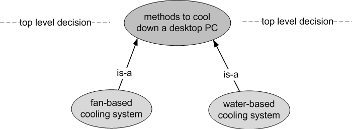 |
| Figure 15. top-level decision - two methods for cooling down a PC from which one is selected |
Structural hierarchy, by comparison, further breaks down each method into their constituent parts with a has-part relationship. This is necessary since it helps engineers map a bigger picture of all design possibilities and hence the stages where decisions are required to be made. The fan and the water-based systems above, then, are broken down into their structural parts. This will create yet more paths that require lower-level decisions to be made. Figure 16 clarifies this division.
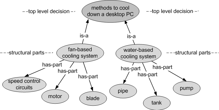 |
| Figure 16. The fan and water-based cooling systems are broken down to their structural parts |
From this point, a second decision level can be drawn before further breakdown of the system. Figure 17 shows this stage with the second decision level.
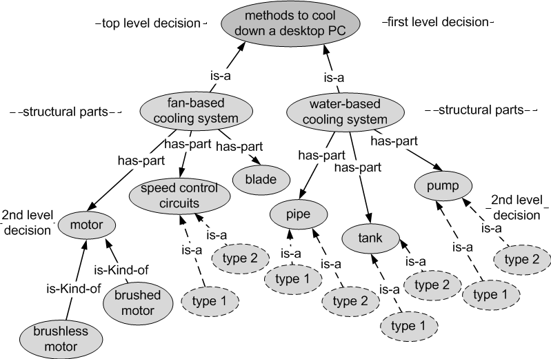 |
| Figure 17. The second level of decisions of the fan and water-based cooling systems |
return top