Logic Circuits
This chapter is dedicated to computer related engineering disciplines. These are: computer, software, telecommunications, and media engineering disciplines. In general, engineering students of these disciplines must have a sufficient understanding of a set of fundamental subjects that are common to these fields. Some of these subjects are:
- Number systems
- Boolean algebra
- Logic gates
Analogue vs. Digital Data Representation
Data can be represented in two different forms, analogue and digital. An example of analogue representation is a bimetallic or liquid-based thermometer. Temperature data in such systems is represented in quantities that are said to be continuous or simply, analogue. It is continuous because the numerical representation of temperature, with the flow of time, is either rising, falling, or it doesn’t change. This means that analogue representation represent data in its natural, continuous form without changing it.
Digital representation, on the other hand, changes the natural form of the data into sets of digits, with each set representing a small portion of the data. The output of digitally represented data is no longer continuous in nature but rather digitised or encoded using a binary number system. This is where the notion of number systems comes in. Engineering students of computer related disciplines must fully understand the different numerical data representations that are used in computerised systems. Although there are quite a few number systems, only a handful of them are used in the world of computer science and engineering. These are: binary, octal, decimal, and hexadecimal number systems.
return top
Number systems
Binary number system
The base of binary number system is two. This means that any number can be represented with only two symbols i.e. 0 and 1. These symbols are called bits. Because of its simplicity, binary number system is used as the fundamental language-unit of computers. These two bits form machine language in which operating systems and computer applications are written. Binary numbers are usually suffixed with the letter B. Examples of binary numbers: 0101B, 0000B, 0001B. Another way to represent binary numbers is by using subscripts: 01012, 00002, 00012. The subscript 2, in here, indicates base 'two' or binary. The table below shows a quick way to generate binary numbers.
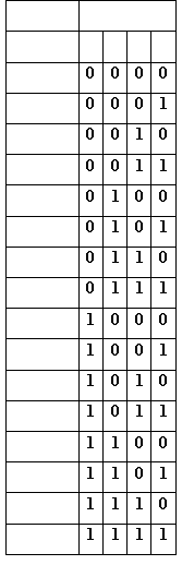 |
The table shows the binary numbers under multiples of 2: 1, 2, 4, 8, 16, etc. For example, 1410 (the subscript 10 means decimal) is a combination of 810 + 410 + 210. We simply place '1' under each of these numbers and '0' for the missing ones to generate the binary. The table can represent binaries between 0-15. Larger numbers requires more multiples of 2 i.e. 16, 32, 64, 128, etc.
Octal number system
The base of octal number system is eight. This means that numbers are represented with eight symbols i.e. 0, 1, 2, 3, 4, 5, 6, and 7. Octal numbers are mainly used to represent file permissions under UNIX and UNIX-like operating systems. It is also sometimes used instead of hexadecimal numbers (Hexadecimal numbers are explained shortly). Octal numbers are usually suffixed with the letter Q. Examples of octal numbers: 133Q, 0Q, 11Q. Another way to represent octal numbers is by using subscripts: 1338, 08, 118. The subscript 8, in here, indicates base eight or octal.
Decimal number system
The base of decimal number system is ten. This means that numbers are represented with ten symbols i.e. 0, 1, 2, 3, 4, 5, 6, 7, 8, and 9. Since the majority of humans understand and use decimal numbers, outputs of computerised systems must first be converted to decimal form and then displayed. Decimal numbers are usually suffixed with the letter D. Examples of decimal numbers: 5D, 10D, 99D. Another way to represent decimal numbers is by using subscripts: 510, 1010, 9910. The subscript 10, in here, indicates base ten or decimal.
Hexadecimal number system
The base of hexadecimal number system is sixteen. This means that numbers are represented with sixteen symbols i.e. 0, 1, 2, 3, 4, 5, 6, 7, 8, 9, A, B, C, D, E, and F. The primary usage of this number system is to represent binary numbers outside computers and computerised systems. This is because binary number system produces long series of '0's and '1's in such a way that it becomes unmanageable for programmers when designing and writing computer programmes. Hexadecimal numbers are usually suffixed with the letter H. Examples of hexadecimal numbers: 9H, CH, 5AH. Another way to represent hexadecimal numbers is by using subscripts: 916, C16, 5A16. The subscript 16, in here, indicates base sixteen or hexadecimal.
Computer scientists and engineers must be able to comfortably convert between these number systems.
return top
Number System Conversion
Conversion to decimal number system
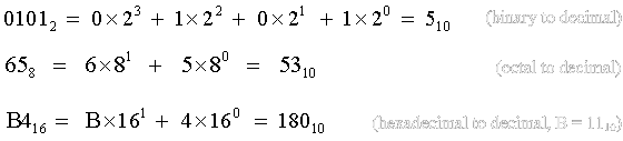
The digits of decimal numbers are arranged next to each other to form larger numbers. The positions of the digits indicate the significance that a particular digit has. Starting from the right-most position, the positions have significance of 100, 101, 102, 103, etc. The number 10 is the base of the decimal number system. But the same rule applies to other number system when we convert them to decimal. Below is how we convert different number systems to decimal:
 |
Conversion from decimal number system
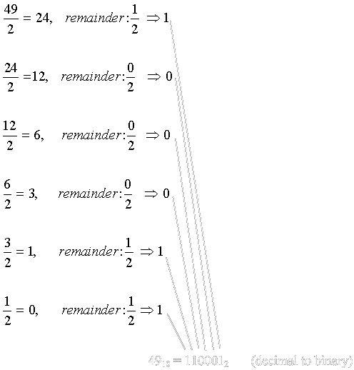
Successive division of a decimal number by any base will produce the same number in that base. For example, successive division of a decimal number by 2 will produce the same number in binary form. The examples below show this conversion.
Convert 4910 to its binary equivalent:
 |
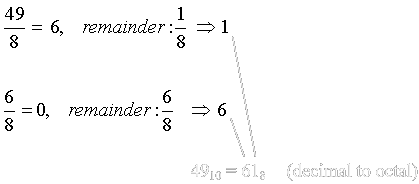
Convert 4910 to its octal equivalent:
 |
Convert 4910 to its hexadecimal equivalent:
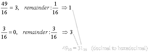 |
Other Conversions
Converting octal and hexadecimal number systems to and from binary number system is straightforward. The examples below show these conversions.
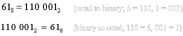
Octal to binary – binary to octal
Each octal digit can be represented with 3 positions (or 3 bits) in binary system. To convert an octal number to a binary number, we simply represent each octal digit with its binary equivalent and combine them. The example below illustrates this conversion.
 |
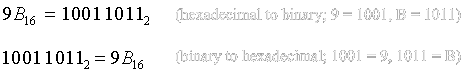
Hexadecimal to binary – binary to hexadecimal
Conversion between hexadecimal and binary number systems is the same as that of octal and binary. Since a hexadecimal digit can be represented with 4 bits of binary number, each of its digits is first converted to a 4-digit binary then combined to form the final result. The example below illustrates this conversion.
 |
Arithmetic of different number systems
The basic ideas and procedures of arithmetic operations is the same for the number systems. Whenever we have a situation in which arithmetic of two numbers produced a number larger than the base of the numbers, a carry is generated. A '1' is also borrowed when subtracting a smaller number from a larger one however, such subtraction require deeper knowledge of the subject which will not be covered here. For example, adding two '1's in binary number will produce a carry of '1'.
Binary arithmetic - addition
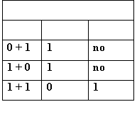 |
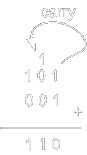
Binary addition example: 1 + 1 = 0, carry = 1
 |
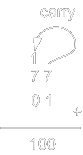
Octal addition example: 7 + 1 = 0, carry = 1
 |
Hexadecimal arithmetic - addition
One way to perform hexadecimal arithmetic is by producing a kind of a ruler as in the figure below.
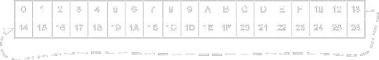 |
With the ruler above, arithmetic operations can easily be performed especially for beginners. The example below shows a hexadecimal arithmetic. Note that F + 1 = 0 with a carry = 1.
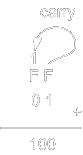 |
return top
Boolean Algebra
Computers are machines that process data for a particular purpose. Data is usually entered to a computer through input devices. Keyboards are examples of input devices. Outputs are directed to output devices such as monitors. Data has to be in the form of binary bits before a computer can process it. Temperature data, for example, has to be first converted to a binary form before a computer can store it and process it. Characters, just like numbers, have to be converted to their binary equivalent too before they can be stored or processed. Same thing for images, videos, etc. But how a computer converts information into a binary form? The answer is: through logic circuits. To design logic circuits that can perform different kinds of functions, however, we need to understand Boolean Algebra.
Boolean algebra is a set of operations that are generally performed on a number of variables. The variables represent binary bits. Capitalised alphabets, such as A, B, and C, are usually used to denote the variables. There are three logic operations that can be performed on binary bits. They are:
- Logic addition: logic addition is not the same as binary addition in that adding two ones will not produce two via carry. Logic addition of two '1's is still '1'. Logic addition can be expressed with either a plus sign '+' or the mathematical union sign '∪'. Example: A + B or . In logic designs and programming, this operation is called OR.
- Logic multiplication: logic multiplication is just like multiplying ones and zeros. The multiplication operator can be denoted by a dot, a mathematical intersection symbol '∩' or simply nothing between the variables. Examples: AB, A∙B, A∩B. In logic designs and programming, this operation is called AND.
- Logic complementation: to complement a binary bit is just to switch its value between '1' and '0'. To denote a complemented variable, a 'NOT' can be placed in front of a variable. Examples: NOT A, NOT B, etc. Another way to express complemented variables is by placing a bar over the variable. Examples: A, B, B. In logic designs and programming, this operation is called NOT.
The inputs and outputs of binary logic operations are usually outlined in a special table called truth table. A truth table contains all the possible values of inputs and outputs of logic operations. Below are the truth tables of the logic operations.
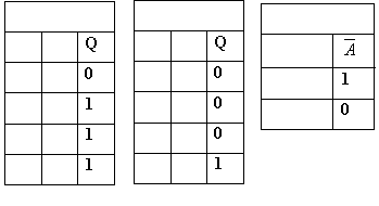 |
In the truth tables above, A and B are the operands or the inputs and Q is the result or output. For example, the logic addition, or logic OR, of 1 + 1 is still '1' (1 OR 1 = 1).
Boolean algebra expressions are fundamental in designing and analysing logic circuits. Based on a set of axioms, complex expression can be simplified and made efficient. Parentheses determine the precedence of logic operations which have the highest order after complementation. Next order of precedence is multiplication which is higher than logic addition.
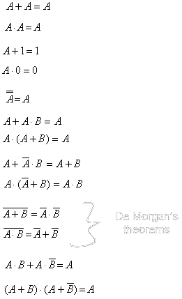
Complex expressions are simplified using Boolean algebra theorems. Below are the main theorems that an IT student should master.
“ Remember that the variables below represent binary bits ‘0’ and ‘1’ ”
 |
Now that we have the theorems we can apply them to simplify the example below.
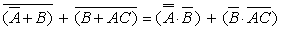
Example 1, simplify the Boolean expression:
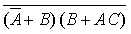 |
Solution:
Using the de Morgan’s theorems:
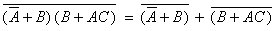 |
We again apply de Morgan’s theorems on each part of the expression:
 |
From the theorems, we know that:
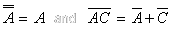 |
then:
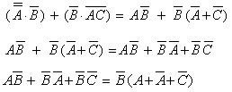 |
Regardless of the value of C, which is either 0 or 1, the expression
(A + A + C) is equal to '1'
since A + A = 1.
This will make the final answer to be just B. Note that this example can also be
solved by simply multiplying the parenthesised expressions.
return top
Digital Circuits
Logic operations AND, OR and NOT have symbols that are used in schematics of logic circuits. They are called logic gates. The gates are as shown in the figure below.
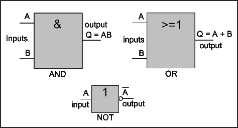 |
| Symbols of AND, OR, and NOT gates |
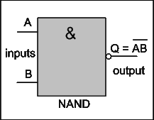
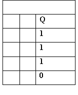
When we combine an AND gate with a NOT gate we produce a gate called NAND. Figure below shows the symbol of NAND gate and its truth table.
 |
 |
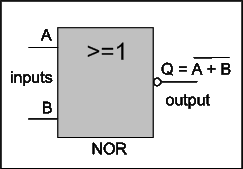
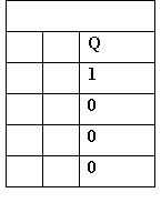
Similarly, when we combine an OR gate with a NOT gate we obtain a NOR gate. The figure below shows the schematic symbol of NOR gate and its truth table.
 |
 |
Note that the symbols of NAND and NOR now have a little circle at their outputs to indicate that the output is inverted with a NOT gate. Another important gate with a combination of the initial logic gates is exclusive OR, or simply XOR gate. Its symbol and truth table are shown next.
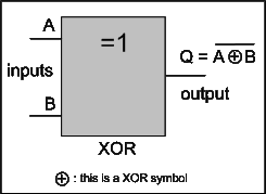 |
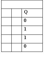 |
Note that the gates can have any number of inputs. Next we will introduce practical examples to clarify the role of Boolean algebra in designing and analysing logic circuits.
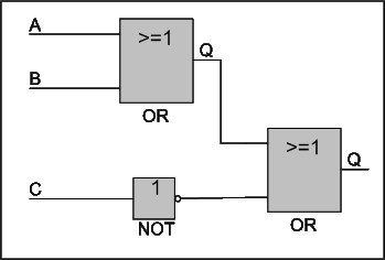
Example 1: consider the circuit below:
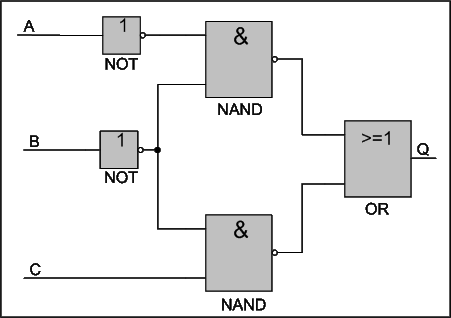 |
We are asked to simplify this circuit and produce a truth table for its inputs and output.
Solution: the way this is accomplished is by first formulating the necessary Boolean expression for the circuit. Then, if possible, apply the Boolean theorems to further simply it and finally, redraw a simpler circuit. These steps are shown next.
Figure below shows the logic circuit with the right expressions at the inputs of the gates and the result at Q at the output of the OR gate.
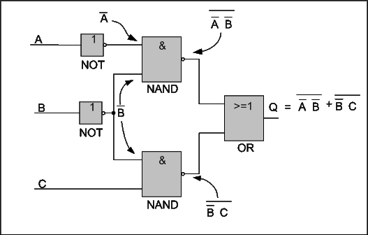 |
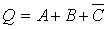
The Boolean expression that we get from this circuit is:
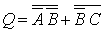 |
We apply Boolean theorem to simplify the expression:
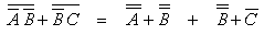 |
We realise that:
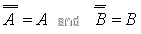 |
The expression then become:
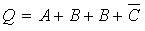 |
But B + B is the same as B hence:
 |
The plus signs tell us that we need OR gates. The bar over C tells us that we need a NOT gate. We redraw the circuit using logic gates explained earlier like below:
 |
The same circuit can be sketched with a three input OR gate like below:
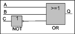 |
The steps above can be summarised in a graph like below:
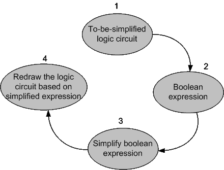 |
| Sketch of the steps that are followed for simplifying a digital circuit design |
The figure shows a four-stage procedure to simplify (or modify) a digital circuit. The first step is to convert the circuit to a Boolean expression. To do that, we write Boolean expressions at the output of each gate by considering expressions of its inputs. After obtaining a Boolean expression, the next step is to apply the Boolean theorems and try to simplify it. The final step is to redraw a modified circuit out of the modified Boolean expression.
To produce a truth table for the circuit, we have to first calculate all possible, input combinations. This is based on the number of inputs of the circuit which is three in this particular case. Three inputs mean 23 which is 8 possible combinations. Then we simply substitute the inputs in the output Boolean expression to produce the Q. Below is the truth table of the circuit.
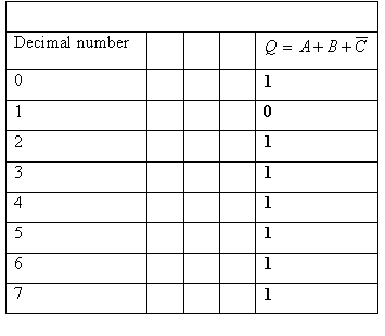 |
As it is shown in the table, the input combinations of the circuit is basically binary numbers between 0-7. The output Q is just the calculation of the inputs substituted in the Boolean expression. We added a column of decimal numbers for clarity.
Example 2: draw the digital circuit defined by the Boolean expression (A+B)C + CB.
Solution: we begin by applying the Boolean theorems to simplify the expression like below:
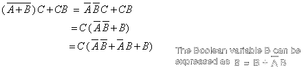 |
But A B+AB is equal to A(B+B) and B+B=1 which results in just A. The expression becomes:
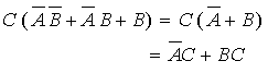 |
Now we can draw the logic circuit defined by like below:
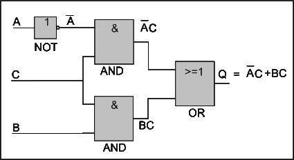 |
return top
Bit Manipulation
Setting, resetting, and complementing bits
We often need to set (change to ‘1’) or reset (change to ‘0’) individual bits out of a series of bits. We can do that with the basic logic operations AND, OR, and XOR. When you multiply or AND a bit with ‘0’ the result is always ‘0’. When you multiply or AND a bit with ‘1’, we get the bit back without change. Logic AND, therefore, resets bits with ‘0’ and retain a bit when ‘1’ is used. To set individual bits, we use logic OR since OR-ing a bit with ‘1’ will always produce ‘1’ and OR-ing with ‘0’ doesn’t result in any changes. Finally, to complement a bit, we use XOR. XOR-ing with ‘1’ will result in a bit complementation. While XOR-ing with ‘0’ will retain the bit. Below are examples of these operations:
Example 1:
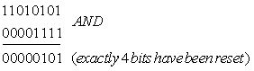
Reset 4 of the left-most bits of the binary bits 1101 0101
Solution: we use the logic AND operation. If we AND the bits with 0000 1111 we should get the right answer since AND-ing with ‘0’ will reset a bit and with ‘1’ will retain it:
 |
Example 2:
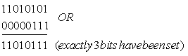
Set the 3 right-most bits of the binary bits 1101 0101
Solution: we use the logic OR operation. If we OR the bits with 0000 0111 we should get the right answer since OR-ing with ‘1’ will set a bit and with ‘0’ will not change:
 |
Example 3:
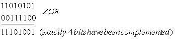
Complement the 4 bits in the middle of the binary bits 1101 0101
Solution: we use the logic XOR operation. If we XOR the bits with 0011 1100 we should get the right answer since XOR-ing with ‘1’ will complement a bit and with ‘0’ will not change:
 |
Shifting and rotating bits
Oftentimes bits are shifted and rotated, in both right and left directions, for a particular purpose. For example, shifting a binary number to the right doubles the number and to the left divides it. But there are other important usage of shifting and rotating of bits such as in registers, which are places for holding bits, and embedded systems.
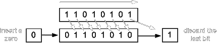
There are two kinds of binary shifts, logical and arithmetic shifts. Shifting to the left for both logical and arithmetic shifts is the same. A ’0’ is inserted to the right-most side of the bits and the rest are shifted one place to the left. Logical shift to the right works the same way; a ‘0’ is inserted to the left-most side of the bits and the rest are shifted to the right side. However, arithmetic shifting to the right is done differently in that, the left-most bits is copied and reinserted to the lft-most side of the bits then the rest of the bits are shifted to the right. Below are examples of these operations:
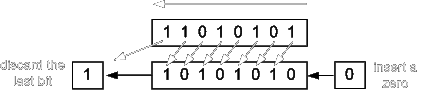 |
| Shift and rotation to the left |
 |
| Rotation to the right |
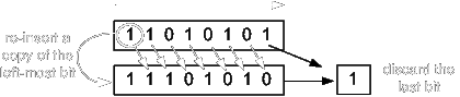 |
| Arithmetic shift to the right |
return top